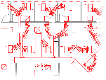
Use the HVAC Plan template to lay out heating, ventilation, and cooling ductwork. You can create HVAC plans on a blank page or as a layer in an existing floor plan.

-
Open Visio.
-
Start an HVAC plan in one of the following ways:
As a new drawing
-
In the Maps and Floor Plans template or category, click HVAC Plan > Create.
By default, this drawing type opens a scaled drawing page in landscape orientation

As a layer in a CAD floor plan
-
Create a new HVAC Plan drawing. Follow the step in the previous section to do that.
-
On the Insert tab, click CAD Drawing.
-
In the Insert AutoCAD Drawing dialog box, navigate to the CAD file, select it, and then click Open.
-
To accept the size and scale of the CAD drawing, click OK.
Note: If the drawing scale of the CAD drawing is different than the scale of your drawing page, you will be asked if you want to match the scales or continue without matching.
-
After you have inserted the drawing, you can resize it, change its scale, or move it. You can also lock the Visio layer that contains the CAD drawing. For more information, see Change AutoCAD layer properties.
Tip: To change the properties of an inserted CAD drawing (for example, to change its scale or protection settings), right-click the drawing, point to CAD Drawing Object, and then click Properties.
As a layer in an existing Visio floor plan
-
In Visio, locate the existing floor plan drawing that you want to use.
Tip: You can lock the existing layers of a drawing so that you do not accidentally change them when you create a new plan on top. For more information, see Change AutoCAD layer properties.
-
-
On the Shapes pane, from HVAC Ductwork, drag the ductwork shapes onto the drawing page.
-
Resize the ductwork shapes.
Resize by stretching
-
Resize duct length or width by dragging selection handles.
-
Resize ducts or change branch angles by dragging control handles.
To see a tip that describes what a control handle on a selected shape does, pause the pointer over the handle.
Resize by entering dimensions
-
Right-click the duct shape, and then click Properties.
-
In the Shape Data dialog box, adjust any of the available dimensions and then click OK.
-
-
Connect ductwork shapes.
-
Position the first ductwork shape on the drawing.
-
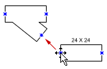
Click and drag a connection point on the second ductwork shape to a connection point on the first ductwork shape.
Note: The pointer must be over or near the connection point that you want connected to the first shape, as shown in the illustration.

-
Release the mouse button when the connection points on both shapes appear as a green square.
Ductwork shapes automatically rotate into position, match the size of the duct to which they are being connected, and glue to each other, as shown in the illustration.

-
To continue connecting ductwork shapes, repeat steps 2 and 3.
Tip: To show or hide connection points, on the View menu, click Connection Points.
-
-
Label ductwork shapes. Simply double-click on the shape and start typing the label text in the text box.
Add a label showing duct size
-
Right-click the duct shape, and then click Show Duct Size.
Note: The diameter symbol (Ø) is added to the label of circular ducts automatically.
-
Reposition a label by dragging the label's control handle.
-
-
Indicate the locations of registers, grills, diffusers, and other HVAC equipment shapes in the drawing.
-
From Registers Grills and Diffusers, drag shapes on top of ductwork or drag shapes onto the drawing page and connect them to the ductwork using a flex duct.
-
From HVAC Equipment, drag shapes on top of ductwork.
Note: Shapes from Registers, Grills and Diffusers and HVAC Equipment are schematic symbols and will not rotate or glue to ductwork.
-
Tip: You can configure some ductwork shapes by right-clicking them and then clicking a command on the shortcut menu. For example, you can change a straight duct from rectangular to circular, and show or hide the duct size.


