
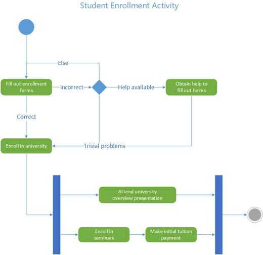
A UML activity diagram in Visio looks like a flow chart. The flow of control is triggered by the completion of actions (or activities) within the system. The flow may be sequential, concurrent, or branched, indicated by shapes such as swimlanes, forks, and joins.
Use an activity diagram to describe how several activities are coordinated to provide a service or other end result. Activity diagrams can show how the events in a use case relate to one another, or how a collection of use cases coordinate to represent a business workflow.
If you want to represent a flow in response to external events instead, use a state machine diagram.
Start an activity diagram
-
Start Visio. Or if you have a file open already, click File > New.
-
In the Search box, type UML activity.
-
Select the UML Activity diagram.
-
In the dialog box, select either Metric Units or US Units.
-
Select Create.
-
The diagram opens. You should see the Shapes window next to the diagram. If you don’t see it, go to View > Task Panes and make sure that Shapes is selected. If you still don’t see it, click the Expand the Shapes window button on the left.
-
On the View tab, make sure the check box next to Connection Points is selected. This option makes connection points appear when you start connecting shapes.
-
You can now insert swimlanes and build the activity control flow in the diagram.
Design your diagram
-
If you want to indicate responsibility in the activity diagram, drag a Swimlane shape onto the page for each class, person, or organizational unit you want to represent. To do that:
-
Drag a Swimlane shape onto the drawing page.
-
Double-click each label on the shape to change the default name.
-
Repeat steps a and b until you've added all the partitions or organizational units you need.
-
Drag the side selection handles on the swimlane shapes to make the lanes the size you want.
-
-
Use the Initial node and Final node shapes to represent initial and final pseudo states.

-
Add an Action shape for each action or activity state you want to represent.
-
Use a Decision shape with guard conditions to indicate a possible transition from an action state.

-
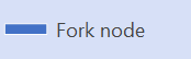
Use the Fork node to represent the forking of one action state into multiple parallel states.
-
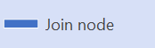
Use the Join node to represent the synchronization of multiple action states into one state.
Note: Creating and editing UML diagrams on Visio for the web requires a Visio Plan 1 or Visio Plan 2 license, which is purchased separately from Microsoft 365. For more information, contact your Microsoft 365 admin. If your admin has turned on "self-service purchasing," you can buy a license for Visio yourself. For more details, see Self-service purchase FAQ.
Start an activity diagram
-
Open Visio for the web.
-
Near the upper right corner of the page, select More templates.
-
Search for UML Activity or scroll down in the Gallery to the UML Activity row.
-
Start with a blank UML activity template or a UML activity starter diagram. Select Create on the one you want to use.
You can now insert swimlanes and build the activity control in the diagram.
Design your diagram
-
If you want to indicate responsibility in the activity diagram, drag a Swimlane shape onto the page for each class, person, or organizational unit you want to represent. To do that:
-
Drag a Swimlane shape onto the drawing page.
-
Double-click each label on the shape to change the default name.
-
Repeat steps a and b until you've added all the partitions or organizational units you need.
-
Drag the side selection handles on the swimlane shapes to make the lanes the size you want.
-
-
Use the Initial node and Final node shapes to represent initial and final pseudo states.
-
Add an Action shape for each action or activity state you want to represent.
-
Use a Decision shape with guard conditions to indicate a possible transition from an action state.
-
Use the Fork node to represent the forking of one action state into multiple parallel states.
-
Use the Join node to represent the synchronization of multiple action states into one state.


