A UML state machine diagram shows the behavior of a part of a designed system. How an object responds to an event depends on the state that object is in. A state machine diagram describes the response of an object to outside stimuli. The object can be a computer program, device, or process.
Note: Creating and editing UML diagrams on Visio for the web requires a Visio Plan 1 or Visio Plan 2 license, which is purchased separately from Microsoft 365. For more information, contact your Microsoft 365 admin. If your admin has turned on "self-service purchasing," you can buy a license for Visio yourself. For more details, see Self-service purchase FAQ.
Following are the shapes on the UML State Machine stencil.
|
Shape |
Description |
|---|---|
|
|
Represents one possible state for the system. |
|
|
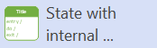
Represents one possible state for the system. After you add it to the diagram, type after each of the "/" characters to specify what actions occur when the system enters the state, while system is in the state, and when the system exists the state. |
|
|
Represents a state that has sub-states, or nested states. Add other state shapes inside the composite shape. |
|
|
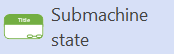
Represents a composite state whose internal details aren't visible. |
|
|
Represents the state of an object before any transitions happen. For an object, this could be the state when it's instantiated. |
|
|
Represents the state of an object in which no transitions lead out of. |
|
|
Represents a conditional branch in the process flow. It evaluates the guards of the triggers of its outgoing transitions to select only one outgoing transition. |
|
|
Used as a diagram comment that has no semantic influence on the model elements. |