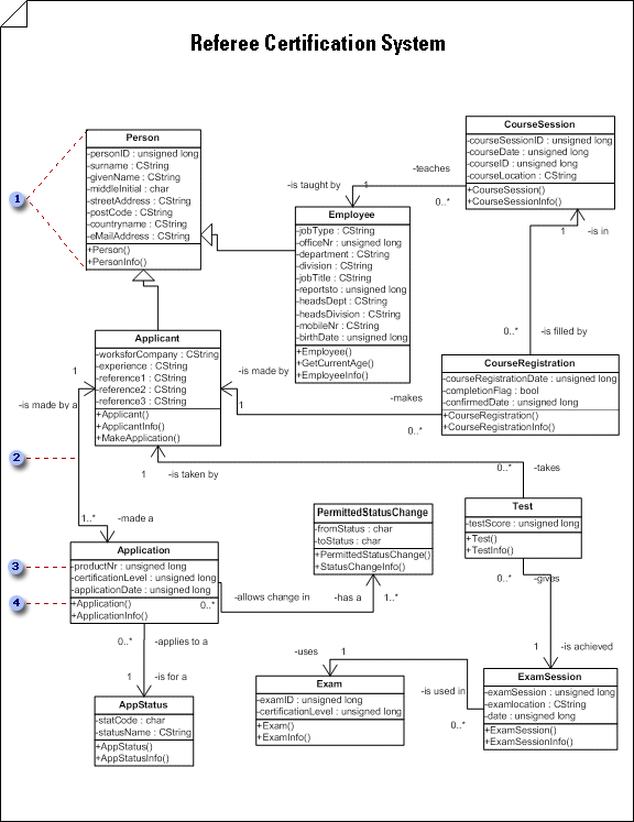
Use a static structure diagram to show a static view of a system's classes, their attributes and methods, and the relationships among objects. It gives an overview of an application.


Important: The UML static structure diagram is not available in Visio 2013 and newer versions. For information, see UML diagrams in Visio.
Start a static structure diagram
-
Select File > New.
-
Under Template Categories, click Software and Database, and then click UML Model Diagram.
-
In the tree view, right-click the package in which you want to include the static structure diagram, point to New, and click Static Structure Diagram.
A blank page appears, and the UML Static Structure stencil becomes the top-most stencil. The workspace displays 'Static Structure' as a watermark. An icon representing the diagram is added to the tree view.
Note: If the tree view isn't visible, point to View on the UML menu, and then click Model Explorer.
-
Drag class or object shapes onto the drawing page to represent the classes or objects you want to include in your class static structure diagram or conceptual model.
Work with classes and objects in UML static structure diagrams
-
Double-click each shape to open its UML Properties dialog box, where you can add attributes, operations, and other properties.
-
Right-click each class or object shape, and then click Shape Display Options to select which properties to display on the shape and which compartments of the shape to suppress (such as attributes, operations, and template parameters).
-
Indicate relationships between the classes and objects using Association, Link, Dependency, Generalization, or Composition shapes.
Work with associations in UML static structure diagrams
Work with dependencies in UML static structure diagrams
-
Double-click each relationship shape (Association, Link, Dependency, Generalization, or Composition) to open its UML Properties dialog box, where you can add association end adornments and other properties.
Create a realizes relationship between two elements in a UML static structure diagram
-
In a static structure diagram, right-click any class shape (Class, Parameterized Class, Utility or MetaClass), click Shape Display Options, and then, under General Options, select Realization Link.
-
Glue the control handle


