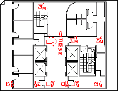
Use the Security and Access Plan template to create drawings that show the positions of access controls and video surveillance equipment.
You can create a security and access plan on a blank page or as a layer in an existing floor plan.

-
Open Visio.
-
Start a security and access plan in one of the following ways:
As a new drawing
In the Maps and Floor Plans category, click Security and Access Plan > Create.
By default, this drawing type opens a scaled drawing page in landscape orientation

As a layer in a CAD floor plan
-
Create a new drawing of the Security and Access Plan template. Follow the step in the previous section if you need information on creating one.
-
On the Insert tab, click CAD Drawing.
-
In the Insert AutoCAD Drawing dialog box, navigate to the CAD file, select it, and then click Open.
-
To accept the size and scale of the CAD drawing, click OK.
Note: If the drawing scale of the CAD drawing is different than the scale of your drawing page, you will be asked to match the scales or continue without matching.
-
After you have inserted the drawing, you can resize it, change its scale, or move it. You can also lock the Visio layer that contains the CAD drawing. For more information, see Change AutoCAD layer properties.
Tip: To change the properties of an inserted CAD drawing (for example, to change its scale or protection settings), right-click the drawing, point to CAD Drawing Object, and then click Properties.
As a layer in an existing Visio floor plan
-
In Visio, locate the existing floor plan drawing that you want to use.
-
-
Drag security shapes for alarm and access control, initiation and annunciation, and video surveillance onto the drawing page.
The letters on the corners of the security shapes indicate the mount type (top right), technology type (bottom right), and function type (bottom left).
Tip: You can lock the existing layers of a drawing so that you do not accidentally change them when you create a new plan on top. For more information, see Change AutoCAD layer properties.
-
You can change shape data at any time.
-
Right-click the shape > Data > Shape Data.
-
In the Shape Data pane, click in each field and type or select a value.
-
-
To label a shape, double-click the shape and then type. Reposition a label by dragging the label's control handle.


