Pierakstīties, izmantojot Microsoft
Pierakstīties vai izveidot kontu
Sveicināti!
Atlasīt citu kontu.
Jums ir vairāki konti
Izvēlieties kontu, ar kuru vēlaties pierakstīties.
angļu
Diemžēl šis raksts jūsu valodā nav pieejams.

Use the Electrical Engineering drawing type in Visio Professional or Visio Plan 2 to create electrical and electronic schematic diagrams.
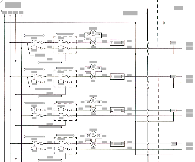
Electrical engineering circuit

  1. On the File tab, select New, and then search for Engineering templates.

  2. Select one of the following:

    • Basic Electrical

    • Circuits and Logic

    • Fluid Power

    • Industrial Control Systems

    • Parts and Assembly Drawing

    • Piping and Instrumentation Design

    • Plumbing and Piping Plan

    • Process Flow Diagram

    • Systems

    • TQM diagram

    • Work Flow Diagram

  3. Choose Metric Units or US Units, and then select Create.

    The template opens an unscaled drawing page in portrait orientation Tall page. You can change these settings at any time.

  4. Drag electrical component shapes onto the drawing page. Shapes can have data. You can enter shape data and add new data to a shape.

    Enter shape data

    1. Select a shape, right-click, select Data, and then select Define Shape Data.

    2. In the Define Shape Data dialog box, select in each item and type or select a value.

  5. Use the Connector tool Button image to connect electrical components or connector shapes.

    Use the Connector tool

    1. Select the Connector tool Button image.

    2. Drag from a connection point Connection point image - blue X on the first shape to a connection point on the second shape. The connector endpoints turn red when the shapes are connected.

    Use connector shapes

    1. Drag a connector shape onto the drawing page.

    2. Place the connector's begin point Begin point image - green square with X inside on the parent shape (the shape you’re connecting from).

    3. Place the connector's end point End point image, which is plus sign in a green square on the child shape (the shape you’re connecting to).

      When the connector is glued to the shapes, the endpoints turn red.

  6. Label individual electrical component shapes by selecting the shape and typing.

Want More?

Find sample electrical engineering Visio templates and diagrams

Nepieciešama papildu palīdzība?

Vēlaties vairāk opciju?

Explore subscription benefits, browse training courses, learn how to secure your device, and more.

Communities help you ask and answer questions, give feedback, and hear from experts with rich knowledge.

Vai šī informācija bija noderīga?

Kas ietekmēja jūsu pieredzi?
Nospiežot Iesniegt, jūsu atsauksmes tiks izmantotas Microsoft produktu un pakalpojumu uzlabošanai. Jūsu IT administrators varēs vākt šos datus. Paziņojums par konfidencialitāti.

Paldies par jūsu atsauksmēm!

×